
Last updated on January 23, 2026
What is Electrical Resistance? The Definitive 2026 Guide
Electrical resistance is one of the most fundamental properties in the world of electricity and electronics. In short, it’s the measure of how much a material opposes the flow of electric current. In my schematics and throughout this article, I’ll refer to it with the uppercase letter R.
Every single component or material in a circuit, from a simple wire to the most advanced microprocessor, has some amount of resistance. Understanding what electrical resistance is and how it works is key to designing, troubleshooting, and repairing any electrical system.
Unit of Measurement for Resistance: The Ohm (Ω)
The standard unit of measurement for resistance is the ohm, and its symbol is the Greek letter omega (Ω). The name is a tribute to Georg Simon Ohm (1784-1854), a German physicist whose groundbreaking work explored the relationship between voltage, current, and resistance. His discoveries culminated in the formulation of the famous Ohm’s Law, the cornerstone of circuit theory.
Conductors and Insulators: Two Sides of the Same Coin
All materials oppose the flow of current to some degree. Based on their resistance value, we classify them into two major groups: conductors and insulators.
- Conductors: These are materials that offer very low resistance, allowing electrons to move through them with ease. They are the foundation of all electrical wiring. Prime examples include silver, copper, gold, and aluminum.
- Insulators: In direct contrast to conductors, insulators have an extremely high resistance that almost completely restricts the flow of electrons. Their function is vital for safety, protecting us from direct contact with live wires. Rubber, glass, dry wood, and most plastics are excellent insulators.
To give you a clearer picture, I’ve put together this comparison table showing the resistivity (ρ)—an intrinsic property of each material that defines its resistive behavior. The lower the resistivity, the better the conductor.
Comparative Table of Material Resistivity (at 68°F / 20°C)
| Material | Type | Resistivity (ρ) in Ω·m |
|---|---|---|
| Silver | Conductor | 1.59 × 10⁻⁸ |
| Copper | Conductor | 1.68 × 10⁻⁸ |
| Gold | Conductor | 2.44 × 10⁻⁸ |
| Aluminum | Conductor | 2.82 × 10⁻⁸ |
| Wood (Dry) | Insulator | 10¹⁰ – 10¹⁴ |
| Glass | Insulator | 10¹⁰ – 10¹⁴ |
| Rubber | Insulator | ~ 10¹³ |
| Teflon (PTFE) | Insulator | > 10¹⁸ |
How to Measure Electrical Resistance: Using a Multimeter
The question of how to measure electrical resistance has a clear answer: with a multimeter set to its ohmmeter function (Ω). However, getting a correct measurement is crucial for both your safety and the accuracy of the reading.
You should never, ever measure resistance on a circuit that is powered on. Doing so will not only give you a completely wrong reading but can also severely damage your multimeter and, far worse, cause a serious accident.
Here are the steps I follow every single time:
- Disconnect the Power: I kill the power by flipping the corresponding circuit breaker. For electronic components, I simply unplug them from their power source.
- Verify Zero Voltage: With my multimeter in voltmeter mode, I double-check that there’s no residual voltage at the points where I’m about to measure.
- Isolate the Component (if possible): To get a precise reading of a specific component (like a resistor or a motor winding), it’s best to desolder or disconnect at least one of its legs. Otherwise, your multimeter will measure the equivalent resistance of the entire circuit connected in parallel with that component.
- Take the Measurement: I select the ohms scale (Ω) on my multimeter, place the probes on the ends of the component or circuit section, and record the reading from the screen.
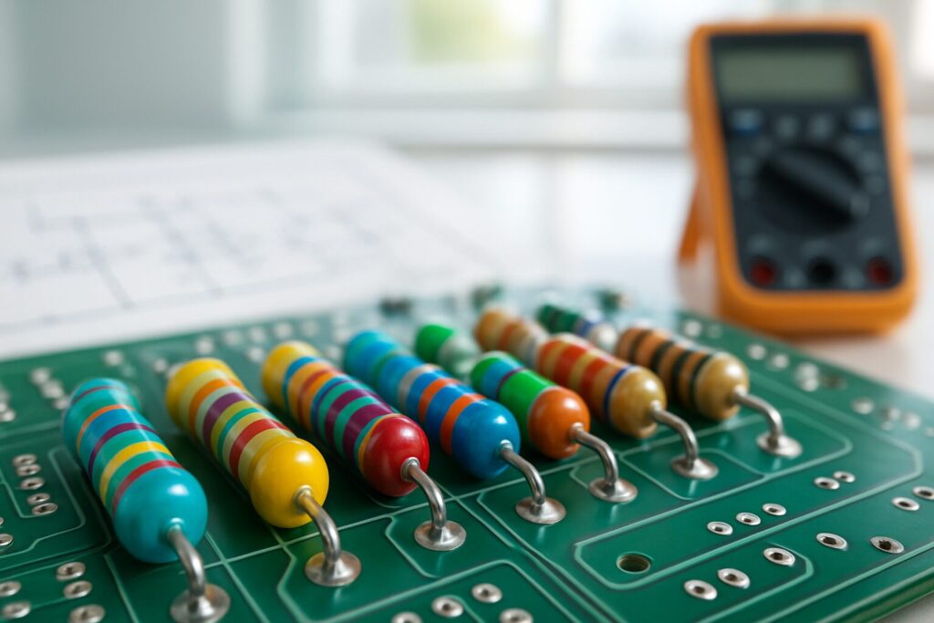
Types of Resistors and Color Codes
In electronics, we use specific components called resistors to precisely control the flow of current. There are many types, but the most common ones you’ll encounter in 2026 are:
- Carbon Film Resistors: Inexpensive and great for general use, though less precise than metal film types.
- Metal Film Resistors: Offer higher precision and stability, making them ideal for sensitive circuits.
- Wirewound Resistors: Made from a resistive wire coiled around a core. They can handle high power and are used in industrial applications.
- SMD (Surface Mount Device) Resistors: Tiny surface-mount components that are ubiquitous in all modern electronics, from smartphones to Zigbee coordinators like the SMLIGHT SLZB-06.
How to Read Resistor Color Codes
Through-hole resistors (not SMDs) have colored bands printed on them to indicate their value. Learning to read them is a fundamental skill for any electronics enthusiast.

Typically, resistors use 4 or 5 bands. You read them starting from the end opposite the tolerance band (which is usually gold or silver).
- 4-Band Resistor: 1st Digit, 2nd Digit, Multiplier, Tolerance.
- 5-Band Resistor (High Precision): 1st Digit, 2nd Digit, 3rd Digit, Multiplier, Tolerance.
| Color | Value (1st/2nd/3rd Band) | Multiplier | Tolerance |
|---|---|---|---|
| Black | 0 | ×1 | – |
| Brown | 1 | ×10 | ±1% |
| Red | 2 | ×100 | ±2% |
| Orange | 3 | ×1k | – |
| Yellow | 4 | ×10k | – |
| Green | 5 | ×100k | ±0.5% |
| Blue | 6 | ×1M | ±0.25% |
| Violet | 7 | ×10M | ±0.1% |
| Grey | 8 | ×100M | ±0.05% |
| White | 9 | ×1G | – |
| Gold | – | ×0.1 | ±5% |
| Silver | – | ×0.01 | ±10% |
How Resistance Behaves in Circuits
The total resistance of a circuit depends not only on the individual component values but also on how they are connected. The two basic arrangements are series and parallel.
Resistors in Series
When components are connected one after another, like cars in a train, we say they’re in series. In this configuration, the current must flow through every single resistor.
The total resistance (RT) is simply the sum of all the individual resistances.
RT = R1 + R2 + R3 + ... + Rn
If we have three resistors of 100 Ω, 220 Ω, and 470 Ω in series, the total resistance will be 100 + 220 + 470 = 790 Ω.
Resistors in Parallel
In a parallel connection, components are wired so that the current splits to pass through each one simultaneously. Imagine several alternate paths for water in a river.
Calculating the total resistance here is a bit more complex, but the key rule to remember is that the total resistance will always be less than the smallest individual resistance.
The formula for total electrical resistance in parallel is:
1/RT = 1/R1 + 1/R2 + 1/R3 + ... + 1/Rn
For just two resistors, the formula simplifies to: RT = (R1 * R2) / (R1 + R2)
For example, with two 100 Ω resistors in parallel, the total resistance would be (100 * 100) / (100 + 100) = 10000 / 200 = 50 Ω.
The Electrical Resistance Formula: Applying Ohm’s Law
As I mentioned earlier, Ohm’s Law is the formula that connects voltage, current, and resistance. It’s an indispensable tool for any technician or electrician.
V = I × R
Where:
- V: Voltage (in Volts, V)
- I: Current (in Amperes, A)
- R: Resistance (in Ohms, Ω)
If we can’t measure resistance directly (for example, in a live, running circuit), we can calculate it if we know the voltage and current. By rearranging the main formula to solve for R, we get:
R = V / I
This calculation is extremely useful for troubleshooting, as we can see in the following examples.
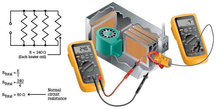
In this circuit, with a voltage of 240V (common for large appliances in the US) and a current of 4A, the normal total resistance is 60 Ω (240 ÷ 4 = 60 Ω). This value serves as our baseline.
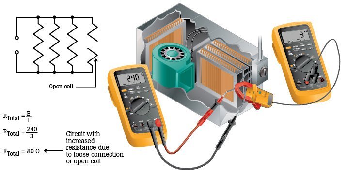
Now, if we measure a current of only 3A, the resistance has increased to 80 Ω (240 ÷ 3 = 80 Ω). This 20 Ω increase could be due to a loose connection, corrosion on a terminal, or partial damage to a heating element. This increase in R restricts the flow of current.
Uses and Applications of Resistance in 2026
Although “resistance” might sound like a bad thing, it’s a phenomenon we constantly leverage in today’s technology:
- Current Limiting: You can’t connect an LED directly to a 5V source because it would burn out instantly. A resistor is used in series to limit the current to a safe value (e.g., 20 mA).
- Heat Generation: The classic toaster is a perfect example. As current passes through the high-resistance coils, it generates the heat that toasts your bread. The same principle applies to hair dryers, electric ovens, and soldering irons.
- Voltage Dividers: Using two resistors in series, we can create an output voltage that is a fraction of the input voltage. This is fundamental for allowing analog sensors to communicate with microcontrollers.
- Smart Home Heating: The electric floor heating or heated towel racks that I integrate into Home Assistant systems rely on this principle to work.
- Device Chargers: Chargers for smartphones and other gadgets use precision resistors to regulate the voltage and current delivered to the battery, ensuring a safe and efficient charge.
Frequently Asked Questions (FAQ)
Is the resistance of a wire always zero?
No. Every conductor, no matter how good, has some resistance, even if it’s very small. For short distances and low currents, this resistance is negligible. However, over very long cable runs or with high currents (like in a main service entrance), the wire’s resistance causes a voltage drop and energy loss as heat, which must be accounted for according to the NEC (National Electrical Code) guidelines in 2026.
What happens if I use a resistor with the wrong power (wattage) rating?
Besides its value in ohms, resistors have a power rating in watts (W) that indicates how much heat they can safely dissipate. If the current and voltage passing through it exceed that power rating (P = V x I = I² x R), the resistor will overheat, burn out, and potentially damage other components in the circuit. Pro Tip: I always recommend using a resistor with a power rating at least double the calculated requirement to build in a safety margin.
Why is it critical to measure resistance with the power off?
I’m repeating this warning because it’s that important. To measure resistance, a multimeter applies a small, known voltage from its own internal battery and measures the resulting current. If there is any external voltage present in the circuit, it will interfere with the measurement and, more importantly, can send a dangerous amount of current back into the multimeter, destroying its internal fuses or, in a worst-case scenario, the meter itself.