

Updated August 23, 2026 · Wiring, boot-strapping GPIOs, ESPHome configuration, placement, and troubleshooting reviewed.
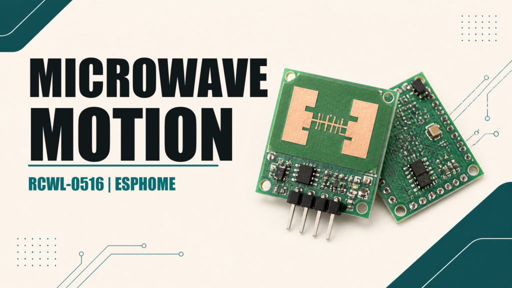
The RCWL-0516 is an inexpensive microwave motion sensor that works with ESPHome and Home Assistant. Unlike a PIR, it does not measure changes in infrared radiation. It emits a low-power radio signal and uses the Doppler effect to detect movement. This means it can be hidden behind thin plastic, wood, or cardboard, but poor placement can also make it detect motion outside the intended area.
This guide connects it to an ESP8266 or ESP32 using a safe GPIO. Older examples often use GPIO2, one of the pins that controls ESP8266 boot mode. It may work in a particular circuit, but it is not a good default for a reliable installation.
What the RCWL-0516 actually detects
This module detects motion, not stationary presence. A person who remains still can stop being detected. It is suitable for switching on a light when someone enters, but a dedicated mmWave presence sensor is a better choice when you must detect someone sitting quietly.
- Motion can be detected through non-metallic materials.
- Metal blocks or substantially changes the detection field.
- A thin partition may not stop it from detecting the next room.
- Fans, vibration, noisy power, or nearby radar modules can cause false triggers.
- Actual range depends on the board, enclosure, orientation, and environment.
Pins and power
| Pin | Purpose | Recommended connection |
|---|---|---|
| VIN | Power input | 5 V from the development board |
| GND | Ground | Common ground with the ESP |
| OUT | Digital motion output | GPIO4 or GPIO5 on ESP8266; a suitable free GPIO on ESP32 |
| 3V3 | Module regulator output | Do not use it to power the RCWL-0516 |
| CDS | Optional light inhibit input | Leave disconnected in this guide |
Common application notes specify roughly 4 to 28 V at VIN and an OUT high level near 3.3 V. Cloned modules do not always use identical components, so check the silkscreen and measure the output when the source is uncertain. Never feed a 5 V signal directly into an ESP8266 or ESP32 GPIO.
Why GPIO2 is best avoided
GPIO0, GPIO2, and GPIO15 select the ESP8266 boot mode. Normal boot requires GPIO0 and GPIO2 high and GPIO15 low. A peripheral connected to one of these pins can alter that state during power-up and prevent the board from starting.
Use GPIO4 (D2) or GPIO5 (D1) on a Wemos D1 mini or NodeMCU. On a classic ESP32, GPIO27 is one possible choice, provided it exists and is free on your exact board. Our Wemos D1 mini pinout and ESPHome guide explains the difference between the GPIO number and the label printed on the board.
RCWL-0516 wiring
- RCWL VIN → 5V on the development board.
- RCWL GND → GND.
- RCWL OUT → GPIO4 (D2) on ESP8266, or GPIO27 in the ESP32 example.
Keep the wires short during testing. A 100 nF decoupling capacitor between VIN and GND near the module can help with noisy power; a 10–100 µF electrolytic capacitor may also help difficult builds. Do not place the antenna against the ESP board, a metal plane, or a metal enclosure.
ESPHome configuration for ESP8266
binary_sensor:
  - platform: gpio
    name: "Radar motion"
    device_class: motion
    pin:
      number: GPIO4
      mode:
        input: true
    filters:
      - delayed_off: 2s
OUT is normally an active-high digital output, so it does not usually require inverted or an internal pull-up. delayed_off prevents a very brief interruption from creating repeated changes. The module already holds its output for a short period, so tune or remove this filter after observing the real device.
ESP32 configuration
binary_sensor:
  - platform: gpio
    name: "Radar motion"
    device_class: motion
    pin:
      number: GPIO27
      mode:
        input: true
    filters:
      - delayed_off: 2s
Do not copy GPIO27 without checking your board. The ESP32 family contains models with different pinouts. ESPHome warns about many strapping pins during validation; use that warning as a reason to choose another GPIO whenever possible.
Placement that reduces false triggers
- Test the uncovered module first and watch the entity in Home Assistant.
- Move it away from switch-mode power supplies, motors, fans, and large metal objects.
- Point the component side toward the intended detection zone.
- Test the room behind it because radar can cross lightweight partitions.
- Only install the final enclosure after tuning the position.
A plastic enclosure hides the board but does not necessarily reduce its range. If it detects the wrong area, adjust orientation first. A metal shield on the unwanted side can help, but keep clearance around the antenna and retest the complete zone.
Troubleshooting
| Problem | Check |
|---|---|
| ESP8266 will not boot | Disconnect the sensor and move from GPIO0/GPIO2/GPIO15 to GPIO4/GPIO5 |
| Motion is always on | Power quality, distance from the ESP, vibration, another radar, or movement behind a wall |
| No detection | 5 V at VIN, common ground, correct OUT pin, and orientation |
| Entity changes too often | Increase delayed_off and improve power |
| Range is excessive | Change position/orientation or shield the unwanted side |
RCWL-0516 or PIR?
The RCWL-0516 is useful when the sensor must be hidden or operate without a visible Fresnel lens. A PIR usually limits detection to a room more predictably and uses less power. Neither is equivalent to a presence radar for stationary occupants. Choosing the right sensor is better than trying to correct a physical limitation in software.