

Updated August 28, 2026.
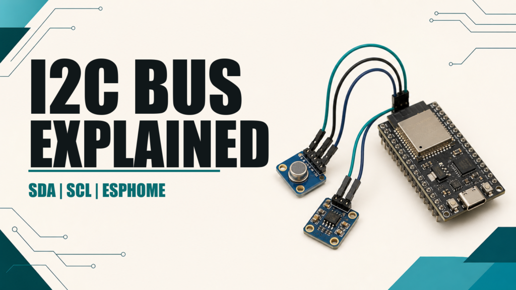
The I²C bus connects several sensors and peripherals to an ESP32 or ESP8266 using only two signals: SDA for data and SCL for the clock. In ESPHome, you define the bus once and each compatible component uses it. Common examples include the BME280, BMP280, and HTU21D.
What I²C is and how it works
I²C is a synchronous serial bus. The controller starts communication and generates the clock; each device responds to an address, usually written in hexadecimal, such as 0x76 or 0x77. Every device shares SDA, SCL, and GND, so you do not need two additional GPIO pins for each sensor.
- SDA: carries data in both directions.
- SCL: provides the communication clock.
- GND: gives all devices a common electrical reference.
- VCC: powers each module at a voltage supported by that board.
Devices can share the same bus as long as their addresses do not conflict. If two modules have the same fixed address, change an address jumper where available, use another supported bus, or add a multiplexer such as the TCA9548A.
Current ESPHome I²C configuration
i2c:
  sda: GPIO21
  scl: GPIO22
  scan: true
  id: main_bus
  frequency: 100kHz
GPIO21 and GPIO22 are common defaults on classic ESP32 boards, but they are not universal. ESP8266 boards often use GPIO4 and GPIO5. Always check the pinout for your exact board; ESPHome can also use defaults provided by the selected board variant.
At boot, scan: true searches the address space and prints detected devices in the log. This is a diagnostic tool, not proof that the component is configured correctly. Seeing 0x76 confirms an electrical response, but you must still choose the correct platform and address.
Adding a sensor to the bus
sensor:
  - platform: bme280_i2c
    i2c_id: main_bus
    address: 0x76
    temperature:
      name: "Living Room Temperature"
    pressure:
      name: "Living Room Pressure"
    humidity:
      name: "Living Room Humidity"
    update_interval: 60s
i2c_id is required only when more than one bus exists, but specifying it makes the configuration easier to understand. The address must match both the scan result and the addresses supported by the component.
Internal and external pull-up resistors
SDA and SCL are open-drain lines: devices pull them low, while pull-up resistors return them high. ESPHome enables internal pull-ups on ESP32, and ESP8266 keeps its internal 10 kΩ pull-ups enabled. The official documentation still recommends external pull-ups for longer wiring or buses with several devices.
Many breakout boards already include pull-ups, commonly between 4.7 kΩ and 10 kΩ. Do not add resistors blindly: several boards place their resistors in parallel, reducing the effective resistance. For a short bus with one or two modules, start with the hardware already fitted and inspect the schematic if errors appear.
Frequency, cable length, and logic level
ESPHome defaults to 50kHz. 100kHz is a standard speed and usually works on short wiring, while a lower frequency can help with slow devices or difficult installations. I²C was designed for short distances inside equipment: keep SDA and SCL short, share GND, and route them away from relays, motors, and mains wiring.
The pull-up voltage sets the bus logic level. With an ESP32 or ESP8266, SDA and SCL should normally be pulled to 3.3 V. Do not assume that a module powered from 5 V automatically performs level shifting; check its schematic first.
Using two I²C buses on ESP32
i2c:
  - id: bus_a
    sda: GPIO21
    scl: GPIO22
    scan: true
  - id: bus_b
    sda: GPIO16
    scl: GPIO17
    scan: true
Some platforms support more than one bus. Separate buses can resolve fixed-address conflicts or isolate a troublesome peripheral. Not every microcontroller and pin pair offers the same capabilities, so validate the configuration for your exact board.
Troubleshooting
- No address appears: check power, common ground, swapped SDA/SCL, and continuity.
- An unexpected address appears: consult the datasheet; some modules select between two addresses with a jumper.
- Intermittent errors: shorten the wiring, reduce frequency, and inspect the pull-ups.
- The bus remains locked: disconnect modules one at a time to find the device holding SDA or SCL low.
- It fails after adding another sensor: check for duplicate addresses and excessive parallel pull-ups.
Conclusion
I²C makes ESPHome projects much simpler, but reliability depends on correct pins, compatible addresses, suitable pull-ups, and short wiring. Enable the scanner during commissioning, confirm each component address, and grow the bus gradually.
Technical sources
Continue reading
Next related guide · 8 min read
ESPHome WiFi: Secure Setup, Roaming and Troubleshooting (2026)
Updated August 5, 2026 for ESPHome 2026.7.3. ESPHome WiFi connects an ESP32 or ESP8266 to your network so it can communicate with Home Assistant,…
Continue with this article