

Updated August 1, 2026. The wiring, GPIO guidance, and configuration have been checked against current ESPHome documentation.
An ESPHome relay module lets an ESP32 or ESP8266 switch loads and expose them as entities in Home Assistant. The basic idea is simple, but three details must never be guessed: the module’s supply voltage, the logic level accepted by its inputs, and the GPIO behavior during startup.
Safety warning: this guide covers only the low-voltage control side. Perform every test with no mains voltage or other hazardous voltage connected to the relay contacts. A mains installation requires the correct enclosure, protection, clearances, conductors, and workmanship. If you are not qualified, have a licensed electrician complete that part.
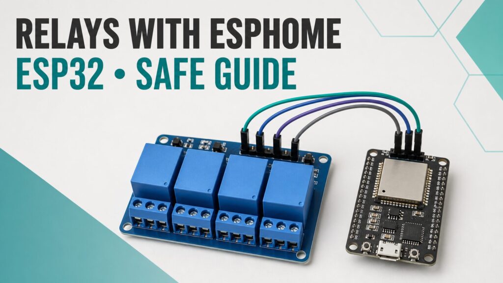
The example uses an ESP32 and a four-channel relay board. It focuses on a reliable ESPHome configuration, a safe first test, and the mistakes that commonly make a relay activate unexpectedly.
What a relay module does
A relay is an electrically operated switch. An IN pin receives the command from the microcontroller, while the separate COM, NO, and NC contacts switch another circuit. NO means normally open; NC means normally closed.
A relay’s isolation does not automatically make an entire module or installation safe. PCB clearances, terminals, enclosure, wiring, and protection must all suit the load. We do not need a load to verify this project: the status LEDs and mechanical click are enough for the first tests.
What you need
- An ESP32 development board supported by ESPHome.
- A documented four-channel relay module.
- A suitable low-voltage supply for the relay board.
- Jumper wires for the control signals.
- A multimeter for voltage and continuity checks.
- ESPHome Device Builder and a Home Assistant installation.
Do not assume that every module labeled “5 V” accepts 3.3 V logic correctly. The 5 V label may describe the relay coils while the control inputs have different requirements. Check the schematic or datasheet for your exact board. If you are new to the platform, start with our Home Assistant guide; the MQ-3 ESPHome project is another practical example of safe analog and power planning.
Choosing ESP32 GPIO pins
There is no universal “available output count” for every ESP32 or ESP8266 board. The chip variant, module, flash or PSRAM, development-board layout, and attached peripherals all change which pins can be used. Some pins are sampled during boot, some connect to flash memory, and GPIO34 through GPIO39 on the original ESP32 are input-only.
For a common ESP32 DevKit based on the original ESP32 without PSRAM, this example uses GPIO16, GPIO17, GPIO18, and GPIO19. Check the pinout for your exact board before wiring and avoid conflicts with I²C, SPI, UART, displays, or other components. Pay attention to ESPHome’s pin warnings instead of suppressing them blindly.
| Channel | Example ESP32 pin | Relay board |
|---|---|---|
| Relay 1 | GPIO16 | IN1 |
| Relay 2 | GPIO17 | IN2 |
| Relay 3 | GPIO18 | IN3 |
| Relay 4 | GPIO19 | IN4 |
Low-voltage relay wiring
- Disconnect every power source before changing the wiring.
- Connect GPIO16, GPIO17, GPIO18, and GPIO19 to IN1, IN2, IN3, and IN4.
- Power the relay board with the voltage specified by its manufacturer. Many mechanical relay modules use 5 V, but designs differ.
- Connect the ground references when the module design requires it. If the board has JD-VCC, a jumper, or optocouplers, follow its schematic because removing or keeping the jumper changes the power and isolation arrangement.
- Leave COM, NO, and NC completely unconnected during programming and initial tests.
Do not power several relay coils from the ESP32’s 3.3 V pin. Their current can exceed what the onboard regulator can deliver and cause resets or unstable behavior. Use a supply sized for the relay board and prevent coil current from pulling down the microcontroller supply.
ESPHome configuration for four relays
Add the following block to the YAML generated for your device. It targets a common active-low relay board: inverted: true makes an ON entity correspond to an energized relay. Remove that line for an active-high module. Confirm the logic with the board LEDs before connecting any load.
switch:
  - platform: gpio
    id: relay_1
    name: "Relay 1"
    pin:
      number: GPIO16
      inverted: true
    restore_mode: ALWAYS_OFF

  - platform: gpio
    id: relay_2
    name: "Relay 2"
    pin:
      number: GPIO17
      inverted: true
    restore_mode: ALWAYS_OFF

  - platform: gpio
    id: relay_3
    name: "Relay 3"
    pin:
      number: GPIO18
      inverted: true
    restore_mode: ALWAYS_OFF

  - platform: gpio
    id: relay_4
    name: "Relay 4"
    pin:
      number: GPIO19
      inverted: true
    restore_mode: ALWAYS_OFF
restore_mode: ALWAYS_OFF tells ESPHome to initialize each switch as OFF. That is a sensible default for a generic guide, but it cannot eliminate a pulse that occurs before the firmware controls the GPIO. Any application where an unexpected activation could cause harm needs a hardware-level safe state.
Compile, install, and run the first test
- Use Validate in ESPHome Device Builder to check the YAML.
- For the first flash, install over USB with the relay module disconnected.
- Power the board down and complete only the low-voltage connections.
- Apply power and watch the ESPHome logs.
- Operate one entity at a time and confirm the correct channel LED and click.
- Reboot and power-cycle the assembly to verify that all four channels remain off during startup.
ESPHome’s native API exposes the four switch entities to Home Assistant automatically. You can rename them, place them in an area, and use them in automations. Adding an ESPHome restart button can also make maintenance easier.
Active-low versus active-high modules
An active-low board energizes a relay when its GPIO is pulled low and normally needs inverted: true. An active-high board energizes it at a high level and does not need that inversion. If Home Assistant says OFF while the relay LED is on, the configured logic is probably reversed.
If all relays click briefly when power is applied, suspect startup pin behavior, floating inputs, or the module’s control circuit. Choose suitable GPIOs, verify the supply, and consider a control stage with defined biasing. Software cannot fix an electrical state that occurs before it takes control.
When relay interlocking is required
Blinds, motors, and bidirectional actuators must not receive both direction commands at once. ESPHome supports software interlocks, but its documentation warns that software alone is not a physical safety guarantee. Use an independent electrical or mechanical interlock and a dead time between directions whenever simultaneous activation could damage a load.
Do not copy the generic four-switch example directly into a reversing-motor project. That application needs a dedicated design that physically prevents both directions from being energized together.
Troubleshooting
The relay does not activate
Measure VCC and GND, confirm that the input accepts 3.3 V logic, and check that the YAML GPIO number matches the physical pin. Test one channel at a time with no loads attached.
The ESP32 resets when a relay switches
An undersized supply, voltage drop, or electrical noise is the likely cause. Improve or separate the relay supply, keep wiring short, and verify the ground arrangement. A YAML change alone will not repair poor power delivery.
The displayed state is reversed
Add or remove inverted: true to match the module’s actual logic. Confirm the result with the LED and relay click rather than relying only on the screen.
The board no longer boots with the module connected
You may have selected a startup or reserved pin, or the relay board may be forcing an invalid level during boot. Disconnect its inputs, recover the ESP32, and check the exact board pinout before assigning new pins.
Video: the original four-relay build
The video shows my original assembly and its practical operation. Use the updated code and safety guidance on this page because they are newer than the recording.
Frequently asked questions
Can I use this configuration with an ESP8266?
Yes, the switch.gpio component is supported, but you must replace the GPIOs with pins suitable for your ESP8266 board. Do not copy the ESP32 numbers or confuse board labels such as D0, D1, and D2 with GPIO numbers.
Do I need a separate relay power supply?
That depends on the module and the main supply. Four coils can draw enough current to destabilize a small regulator or weak USB supply. Follow the relay-board datasheet and leave sensible current margin.
What happens if Home Assistant goes offline?
The ESP32 continues running its firmware. However, if every command comes from Home Assistant, remote control is unavailable until communication returns. Critical functions need independent local controls and safe states.
Conclusion
A four-channel ESPHome relay module is a flexible way to add outputs to Home Assistant. The YAML is short; the important work is choosing suitable GPIOs, identifying active-low or active-high inputs, providing stable power, and deciding what must happen during a restart.
Begin with low-voltage tests and leave the relay contacts empty. Once every channel responds correctly and startup behavior is predictable, design the final application with the protection and enclosure it requires.
Technical sources
- ESPHome GPIO Switch.
- ESPHome Switch Component and restore_mode.
- ESPHome FAQ: strapping pins.
- Espressif ESP32 GPIO reference.
- ESPHome physical connection and safety guidance.
If this guide helped, you can subscribe to TecnoYFoto on YouTube for more practical projects.
Continue reading
Next related guide · 7 min read
MH-RD Rain Sensor with ESP32 and ESPHome: Updated Guide
Updated August 2, 2026. The MH-RD rain sensor is an inexpensive way to detect when a surface starts getting wet and send that information…
Continue with this article