

This article may contain affiliate links. If you buy through these links, the price is the same for you and the store pays me a small commission that helps keep Tecnoyfoto running.

A UPS, or uninterruptible power supply, keeps connected equipment powered during an outage. Depending on its design, it also conditions the power delivered to that equipment. When it protects your NAS, computer, router, or Home Assistant server, useful monitoring goes beyond a power LED: you want battery readings, load, operating mode, and fault indications.
This guide shows how to connect a Salicru UPS to Home Assistant using Modbus TCP. The connection stays on your local Ethernet network and uses Home Assistant’s built-in Modbus integration. You do not need a custom integration or HACS for this example. We used Nimbus to compare readings; Home Assistant reads the UPS directly.
Our tested hardware is a Salicru SLC-1000-TWIN RT3, with UPS firmware 00.01.15485 and IoT firmware 02.02.000. The configuration was validated with Home Assistant Core 2026.10.1 in October 2026. It provides 18 useful entities: eight numeric measurements, operating mode, three presence/power indicators, and six selected alarms. Three additional entities hold the raw mode and status words. This is a verified example for one unit, not a compatibility promise for every Salicru product.
For US readers: the screenshots show readings from our 230 V/50 Hz installation. Those are observed values, not settings to apply to a US electrical system. Use a UPS with the appropriate ratings for your installation, and check its model-specific documentation. Do not change voltage or frequency settings to make a screenshot match.
Step 0. Restart internal IoT from the UPS display
If you are following this guide with a Salicru SLC-1000-TWIN RT3, start by restarting the communications module. On the UPS LCD, select Control → Reinicio IoT interno (internal IoT restart) and confirm. When the display shows “Hecho” (done), wait for the module to come back online. Then continue with the model and IP checks and enable Modbus TCP.
Communication with the module will pause during the restart. If you have a different UPS variant, check that its display offers this function and verify what it does on your unit.
This restart allowed us to move forward on two separate occasions. The HTTPS portal reopened after a connection error, and Modbus responded on port 502 after the restart described in step 4.
What you need before starting
- A Salicru UPS with an accessible Modbus TCP server, either built in or provided by a compatible communications accessory, and the matching register map.
- An Ethernet connection and a network path from Home Assistant to the UPS.
- Legitimate access to the UPS settings, plus permission to edit Home Assistant configuration files.
- A backup and an editor for
configuration.yamland package files. - Basic YAML knowledge: indentation uses spaces, not tabs.
- Time to verify readings before using them in equipment-protection automations.
This setup does not require USB, a NUT server, or cloud polling. The UPS, Home Assistant, and the required network devices must still be operating. If you want notifications during an outage, check that the network and notification path remain powered; local sensor data alone does not guarantee that an alert can leave your home.
Step 1. Check the exact model and Modbus compatibility
Read the label and identification menu. Note the exact model, power rating, firmware versions, and communications hardware. An Ethernet jack does not automatically mean Modbus TCP, SNMP, or a usable monitoring API. Built-in IoT Ethernet and an optional network card can expose different services and maps.
| Hardware or method | Evidence | What still needs checking |
|---|---|---|
| Our SLC-1000-TWIN RT3 | Built-in Modbus TCP and the entities in this guide work on our unit. | Equivalent behavior on your hardware and firmware. |
| RT3 family / IQ14700 | The appendix has a 1–3 kVA column despite the 4–10 kVA cover. | That the listed registers apply to your transport and model. |
| Optional communications card | Services depend on the card and its firmware. | Card model, TCP port, Unit ID, and its own map. |
| Other Salicru / USB | May use another protocol or NUT. | Actual driver and variable support; do not reuse this YAML blindly. |
Use the RT3 EL22650 manual, EL28450 connectivity manual, and IQ14700 register map. Check the applicable table column, not just a document title. These manufacturer documents may open in Spanish. The technical references remain the same as those used in our tests.
USB/NUT is a separate route. The NUT compatibility list includes the RT3 family with experimental usbhid-ups support, but we have not tested this unit over USB. Home Assistant’s NUT integration needs a running NUT server; it is not a direct USB-to-Modbus converter.
Step 2. Find the UPS IP address and keep it stable
Find the UPS in your router’s client list, or read its Ethernet address on the display or local portal. Every example below uses 192.168.1.50, a fictional address. Replace it with the address of your own UPS. No address shown here identifies the network used for our tests.
For a DHCP client, a DHCP reservation in the router helps keep the address unchanged. A reservation is not the same as manually configuring a static address on the UPS. We observed DHCP in our portal and did not change it to obtain a successful reading. Reserving the address is a reproducibility recommendation, not a prerequisite we modified during testing.
Make sure Home Assistant can reach that address. On separate VLANs, review routing and the specific destination/port rules. Do not open every port or disable your firewall globally. A successful test from a laptop does not prove that Home Assistant has the same network path.
If the IP address is correct but the portal will not open
Open https://UPS_IP/if/login using the address confirmed in your router. If you see ERR_CONNECTION_RESET, check that the module is back online after the restart in step 0. For a certificate warning, see step 3.
Step 3. Enable Modbus TCP and verify that the setting persists
On our IoT setting portal, we signed in at https://UPS_IP with our own credentials and found Settings → Network → Access Control → Modbus TCP. We changed Disable to Enable, saved, and reloaded the page to verify persistence. We did not change the timeout, whitelist, CORS, HTTP, or remote-debug settings to make the read work.
The RT3 manual also lists Modbus TCP in the LCD settings and documents it as disabled by default. We checked that the physical display reported it enabled. Menu labels can vary: use the manual for your model and legitimate access, not guessed default passwords or PINs.
The event log recorded Modbus TCP enabled. That confirms the configuration event, but Operational in an event is not a listening-port test. An enabled setting and an accessible TCP service are different things.
If the browser blocks the portal
Our device certificate used a name different from the address we entered and had an untrusted issuer. Kaspersky explicitly blocked it. Saving a narrowly scoped exception for the known device removed that antivirus block, while a separate browser certificate warning remained. The exception did not repair the certificate. Verify the destination first; do not install unknown certificate authorities or disable protection for the whole network.
A blank page is not necessarily a login problem. We found that essential JavaScript had failed to load: an HTTP 200 response for the HTML alone did not mean the application worked. We did not establish that every earlier connection reset had the same cause.
Step 4. Troubleshoot an enabled service that rejects port 502
This was our main obstacle. Enable remained saved, the LCD showed Modbus enabled, and the event log confirmed activation, but TCP port 502 still returned connection refused. A second machine on the same LAN got the same result. This was not enough evidence to blame one browser or computer antivirus.
The failure occurred before a Modbus request could be sent. Changing the register or Unit ID could not fix that TCP refusal. We did not scan addresses or units, update firmware, or change access filters by trial and error.
What worked for us: restarting internal IoT from the physical LCD
We shut down the PC and NAS normally before intervening. On the physical UPS LCD, we used Control → Reinicio IoT interno (internal IoT restart). The display confirmed “Hecho” (done). We checked that Modbus remained enabled and repeated the same minimal read. It now returned a valid response.
This was not a browser action. Restarting the IoT module is not equivalent to restarting or shutting down the whole UPS, and it is not a factory reset. We observed no loss of output power on our unit. That observation is not a safety guarantee for another model, hardware revision, or firmware.
Do not treat this as a mandatory universal step. Before using a control menu, identify the exact function in the device documentation and prepare the protected equipment for a possible interruption. Stop if the menu or consequences are unclear. We established a before-and-after sequence, not the internal cause of the blocked service.
Step 5. Perform one documented read-only request
From Windows, this checks whether TCP port 502 is reachable from that computer. Replace the fictional address:
Test-NetConnection -ComputerName 192.168.1.50 -Port 502TcpTestSucceeded: True proves TCP connectivity, not correct Modbus data. Our first successful request used Unit ID 1, function FC03, PDU address 43, and one 16-bit register. The raw value was 500. Frequency values are expressed in tenths of a hertz, so 500 × 0.1 = 50.0 Hz, matching the output frequency displayed by Nimbus.
The manual’s ModScan example displays addresses with a +1 offset. That is a display convention, not a rule to add one in every client. We used 43 in the PDU and 43 in Home Assistant. Check whether your map counts from zero, counts from one, or includes a prefix such as 40001.
Optional Python test: one FC03 request, no retries
Save this as lectura_salicru.py on a computer with Python 3. It is the read-only script adapted from our tested tool: fixed FC03, register 43, one word, TCP 502, and an explicit host and Unit ID. It validates the response header and length and does not contain battery tests or write functions. Its diagnostic messages and JSON keys retain the original Spanish labels; the request and raw values are language independent.
"""Preparación y lectura única FC03 del registro RO 43. Sin dependencias externas."""

import argparse
import datetime
import json
import socket
import struct
import time

HOST = None
PORT = 502
ADDRESS = 43
TRANSACTION = 1
TIMEOUT = 3.0


def request_frame(unit):
    if not 1 <= unit <= 255:
        raise ValueError("Unidad fuera de rango; no se admite unidad 0.")
    # La única función y dirección posibles están fijadas aquí.
    pdu = struct.pack(">BHH", 3, ADDRESS, 1)
    return struct.pack(">HHHB", TRANSACTION, 0, len(pdu) + 1, unit) + pdu


def decode_frame(frame, unit):
    if len(frame) < 7:
        raise ValueError("Cabecera incompleta.")
    transaction, protocol, length, response_unit = struct.unpack(">HHHB", frame[:7])
    if (transaction, protocol, response_unit) != (TRANSACTION, 0, unit):
        raise ValueError("La cabecera no corresponde a esta petición.")
    if len(frame) != length + 6:
        raise ValueError("Longitud de respuesta incoherente.")
    pdu = frame[7:]
    if len(pdu) == 2 and pdu[0] == 0x83:
        return {"resultado": "excepcion_modbus", "codigo": pdu[1]}
    if len(pdu) != 4 or pdu[:2] != b"\x03\x02":
        raise ValueError("No es una respuesta FC03 de un registro.")
    raw = struct.unpack(">H", pdu[2:])[0]
    return {
        "resultado": "respuesta_fc03",
        "bytes_dato_hex": pdu[2:].hex(" "),
        "valor_uint16": raw,
        "frecuencia_hz_segun_mapa_pendiente_de_contraste": raw / 10,
    }


def recv_exact(connection, count, deadline):
    data = bytearray()
    while len(data) < count:
        remaining = deadline - time.monotonic()
        if remaining <= 0:
            raise TimeoutError("Se agotó el plazo total de recepción.")
        connection.settimeout(remaining)
        part = connection.recv(count - len(data))
        if not part:
            raise ConnectionError("El servidor cerró la conexión antes de completar la respuesta.")
        data.extend(part)
    return bytes(data)


def main():
    parser = argparse.ArgumentParser(description=__doc__)
    parser.add_argument("--host", required=True, help="IP local de tu SAI")
    parser.add_argument("--unit-id", type=int, choices=range(1, 256), metavar="1..255")
    parser.add_argument("--ejecutar", action="store_true", help="Abre la conexión y envía una sola petición; requiere autorización previa.")
    args = parser.parse_args()
    global HOST
    HOST = args.host
    if args.ejecutar and args.unit_id is None:
        parser.error("La ejecución requiere --unit-id; no se elige ni se busca automáticamente.")
    result = {
        "fecha_utc": datetime.datetime.now(datetime.timezone.utc).isoformat(),
        "destino": HOST,
        "puerto_candidato": PORT,
        "unit_id": args.unit_id,
        "funcion": 3,
        "direccion_pdu_decimal": ADDRESS,
        "cantidad_registros": 1,
        "modo": "ejecucion_autorizada" if args.ejecutar else "preparacion_sin_red",
    }
    request = request_frame(args.unit_id) if args.unit_id is not None else None
    if request is not None:
        result["peticion_hex"] = request.hex(" ")
    if not args.ejecutar:
        result["nota"] = "No se ha abierto ninguna conexión. El Unit ID nativo sigue pendiente de validación."
        print(json.dumps(result, ensure_ascii=False, indent=2))
        return 0
    try:
        # Una conexión, una petición, sin reintentos ni sondeo periódico.
        with socket.create_connection((HOST, PORT), timeout=TIMEOUT) as connection:
            connection.settimeout(TIMEOUT)
            connection.sendall(request)
            deadline = time.monotonic() + TIMEOUT
            header = recv_exact(connection, 7, deadline)
            transaction, protocol, length, response_unit = struct.unpack(">HHHB", header)
            if (transaction, protocol, response_unit) != (TRANSACTION, 0, args.unit_id):
                raise ValueError("Cabecera no correspondiente; se cierra la conexión.")
            if length not in (3, 5):
                raise ValueError("Longitud inesperada; se cierra la conexión sin nuevas peticiones.")
            frame = header + recv_exact(connection, length - 1, deadline)
            result["respuesta_hex"] = frame.hex(" ")
            result.update(decode_frame(frame, args.unit_id))
    except (OSError, ValueError) as error:
        result.update(resultado="lectura_no_validada", detalle=str(error))
        print(json.dumps(result, ensure_ascii=False, indent=2))
        return 1
    print(json.dumps(result, ensure_ascii=False, indent=2))
    return 0 if result["resultado"] == "respuesta_fc03" else 1


if __name__ == "__main__":
    raise SystemExit(main())
python lectura_salicru.py --host 192.168.1.50 --unit-id 1
python lectura_salicru.py --host 192.168.1.50 --unit-id 1 --ejecutarThe first command only prints preparation information; it does not open a network connection. Adding --ejecutar sends one request. A respuesta_fc03 result means a valid protocol response, not a validated register map. Preserve exceptions or unexpected values and investigate before continuing. Do not run this fixed-register test against a different model without supporting documentation.
Step 6. Configure the first Home Assistant sensor
For this device we use the built-in Modbus integration with a YAML package, matching our working installation. No custom integration installation is required. Back up your configuration first; do not replace unrelated settings.
6.1. Load a packages directory
If you have not used packages before, or want to understand how to group a device’s configuration in one file, see our guide to organizing Home Assistant with packages. It provides useful context for keeping the Salicru sensors and templates together before you continue with this example.
In configuration.yaml, add this structure only if it is not already configured:
homeassistant:
  packages: !include_dir_named packages
If homeassistant: already exists, merge packages into that section while keeping its other options. Do not create a duplicate homeassistant key. If you already load packages another way, use your existing layout. We already had !include_dir_named packages enabled.
Create a packages directory next to configuration.yaml, then create salicru_modbus.yaml inside it. The package contains modbus: and later template: at its top level. It does not need an extra wrapper key named after the package. See the official packages documentation.
6.2. Start with output frequency only
modbus:
  - name: salicru_rt3
    type: tcp
    host: 192.168.1.50
    port: 502
    timeout: 3
    message_wait_milliseconds: 200
    sensors:
      - name: Salicru Output Frequency
        unique_id: salicru_rt3_frequencia_sortida
        device_address: 1
        address: 43
        input_type: holding
        data_type: uint16
        scale: 0.1
        precision: 1
        unit_of_measurement: Hz
        device_class: frequency
        state_class: measurement
        scan_interval: 60
Replace the IP address and verify the TCP port and Unit ID. type: tcp means Modbus TCP with an MBAP header, not RTU over TCP. input_type: holding selects FC03. device_address is the Unit ID; older configurations may use slave. The documented frequency is two bytes, so uint16 reads one word; do not add a separate count for that data type.
We poll every 60 seconds and leave 200 ms between messages. This is our working configuration, not a manufacturer-wide timing requirement. Minute-by-minute polling is not real-time event capture and cannot guarantee detection of every brief power interruption.
6.3. Validate, restart Core, and inspect the entity
Use the configuration check available under Developer tools → YAML in your Home Assistant version. Fix indentation, duplicate keys, and invalid options before restarting. Restart Home Assistant Core, not the UPS. These examples target Core 2026.10.1; consult the Modbus documentation for other versions.
After startup, open Developer tools → States, search for salicru, and inspect sensor.salicru_output_frequency. Entity IDs may differ if names were already taken or renamed. Do not use “Set state” to make the expected value appear; that does not prove communication with the UPS.
Step 7. Add the tested measurements and operating mode
Once the first reading makes sense, replace the contents of the same package with the complete version below. Do not keep both a minimal package and a full package with the same hub and entities. Do not paste a second modbus: section into the main file.
| Measurement | PDU | Data type | Scale / unit | Validation |
|---|---|---|---|---|
| Output frequency | 43 | uint16 | × 0.1 Hz | 500 → 50.0 Hz; matched Nimbus. |
| Output voltage | 59 | uint16 | × 0.1 V | Close to Nimbus; readings were not simultaneous. |
| UPS load | 63 | uint16* | × 1 % | Plausible changing readings, not a calibration test. |
| Battery charge | 64 | uint16* | × 1 % | 100%; matched Nimbus. |
| Battery voltage | 68 | uint16 | × 0.1 V | 39.4 V; matched Nimbus. |
| Input voltage | 33 | uint16 | × 0.1 V | Responds and updates in HA; compared for plausibility. |
| Input frequency | 29 | uint16 | × 0.1 Hz | 50 Hz, consistent with reference screenshots. |
| Output current | 41 | uint16 | × 0.1 A | 0.4–0.7 A in HA; about 0.6–0.7 A seen in Nimbus. |
| Operating mode | 62 | uint16* | Code | 3 = Line observed; other transitions not tested. |
* One-byte fields: the map describes load, battery charge, and mode as one-byte values. Our FC03 responses put the useful byte in the low byte and zero in the high byte of a 16-bit word. That is the observed format used here, not proof for every firmware implementation. Keep decimal points in YAML even when your interface displays decimal commas.
Mode codes: documented does not mean every transition was tested
| Code | Meaning | Test status |
|---|---|---|
| 0 | Power-on startup | Documented only. |
| 1 | Standby | Documented only. |
| 2 | Bypass | Documented only. |
| 3 | Line | Observed on our unit. |
| 4 | Battery | Documented; no forced outage. |
| 5 | Battery test | Documented; no test started. |
| 6 | Reserved | Do not invent an operating state. |
| 7 | Converter | Documented only. |
| 8 | ECO | Documented only. |
The example uses English names and entity IDs. The screenshots are from our installation, where some names are in Catalan. For a second UPS, use distinct hub names, entity names, and unique_id values.
Complete package: 18 useful entities
This includes eight measurements, a raw mode code, two raw status words, a text mode sensor, and nine binary sensors. The alarms share the same raw status words; they do not require nine additional UPS requests per cycle. Replace the fictional IP, save a backup, and validate before loading it.
# Example for the Salicru SLC TWIN RT3. Replace the IP address with your UPS IP.
# Local monitoring: FC03 reads only. Battery runtime has yet to be verified.
modbus:
  - name: salicru_rt3
    type: tcp
    host: 192.168.1.50
    port: 502
    timeout: 3
    message_wait_milliseconds: 200
    sensors:
      - name: Salicru Output Frequency
        unique_id: salicru_rt3_frequencia_sortida
        device_address: 1
        address: 43
        input_type: holding
        data_type: uint16
        scale: 0.1
        precision: 1
        unit_of_measurement: Hz
        device_class: frequency
        state_class: measurement
        scan_interval: 60
      - name: Salicru Output Voltage
        unique_id: salicru_rt3_tensio_sortida
        device_address: 1
        address: 59
        input_type: holding
        data_type: uint16
        scale: 0.1
        precision: 1
        unit_of_measurement: V
        device_class: voltage
        state_class: measurement
        scan_interval: 60
      - name: Salicru UPS Load
        unique_id: salicru_rt3_carrega
        device_address: 1
        address: 63
        input_type: holding
        data_type: uint16
        precision: 0
        unit_of_measurement: '%'
        state_class: measurement
        scan_interval: 60
      - name: Salicru Battery Level
        unique_id: salicru_rt3_bateria
        device_address: 1
        address: 64
        input_type: holding
        data_type: uint16
        precision: 0
        unit_of_measurement: '%'
        device_class: battery
        state_class: measurement
        scan_interval: 60
      - name: Salicru Battery Voltage
        unique_id: salicru_rt3_tensio_bateria
        device_address: 1
        address: 68
        input_type: holding
        data_type: uint16
        scale: 0.1
        precision: 1
        unit_of_measurement: V
        device_class: voltage
        state_class: measurement
        scan_interval: 60
      - name: Salicru Mode Code
        unique_id: salicru_rt3_codi_mode
        device_address: 1
        address: 62
        input_type: holding
        data_type: uint16
        precision: 0
        scan_interval: 60


      - name: Salicru Input Voltage
        unique_id: salicru_rt3_tensio_entrada
        device_address: 1
        address: 33
        input_type: holding
        data_type: uint16
        scale: 0.1
        precision: 1
        unit_of_measurement: V
        device_class: voltage
        state_class: measurement
        scan_interval: 60
      - name: Salicru Input Frequency
        unique_id: salicru_rt3_frequencia_entrada
        device_address: 1
        address: 29
        input_type: holding
        data_type: uint16
        scale: 0.1
        precision: 1
        unit_of_measurement: Hz
        device_class: frequency
        state_class: measurement
        scan_interval: 60
      - name: Salicru Output Current
        unique_id: salicru_rt3_corrent_sortida
        device_address: 1
        address: 41
        input_type: holding
        data_type: uint16
        scale: 0.1
        precision: 1
        unit_of_measurement: A
        device_class: current
        state_class: measurement
        scan_interval: 60
      - name: Salicru Status Register 1
        unique_id: salicru_rt3_registre_estat_1
        device_address: 1
        address: 1
        input_type: holding
        data_type: uint16
        precision: 0
        scan_interval: 60
      - name: Salicru Status Register 5
        unique_id: salicru_rt3_registre_estat_5
        device_address: 1
        address: 5
        input_type: holding
        data_type: uint16
        precision: 0
        scan_interval: 60


# If the source sensor is unavailable, the alarm must also be unavailable.
template:
  - sensor:
      - name: Salicru UPS Operating Mode
        default_entity_id: sensor.salicru_ups_operating_mode
        unique_id: salicru_rt3_mode_sai
        icon: mdi:power-plug
        availability: "{{ is_number(states('sensor.salicru_mode_code')) }}"
        state: >-
          {% set modes = {0: 'Starting up', 1: 'Standby', 2: 'Bypass',
                          3: 'Online', 4: 'Battery', 5: 'Battery Test',
                          6: 'Reserved', 7: 'Converter', 8: 'ECO'} %}
          {% set code = states('sensor.salicru_mode_code') | int(-1) %}
          {{ modes.get(code, 'Unknown code (' ~ code ~ ')') }}
  - binary_sensor:
      - name: Salicru Utility Power Present
        default_entity_id: binary_sensor.salicru_utility_power_present
        unique_id: salicru_rt3_xarxa_present
        device_class: power
        availability: "{{ is_number(states('sensor.salicru_status_register_5')) }}"
        state: "{{ (states('sensor.salicru_status_register_5') | int(0) | bitwise_and(16384)) != 0 }}"
      - name: Salicru Output Powered
        default_entity_id: binary_sensor.salicru_output_powered
        unique_id: salicru_rt3_sortida_alimentada
        device_class: power
        availability: "{{ is_number(states('sensor.salicru_status_register_5')) }}"
        state: "{{ (states('sensor.salicru_status_register_5') | int(0) | bitwise_and(8)) != 0 }}"
      - name: Salicru Battery Present
        default_entity_id: binary_sensor.salicru_battery_present
        unique_id: salicru_rt3_bateria_present
        availability: "{{ is_number(states('sensor.salicru_status_register_1')) }}"
        state: "{{ (states('sensor.salicru_status_register_1') | int(0) | bitwise_and(1)) != 0 }}"
      - name: Salicru Low Battery
        default_entity_id: binary_sensor.salicru_low_battery
        unique_id: salicru_rt3_bateria_baixa
        device_class: battery
        availability: "{{ is_number(states('sensor.salicru_status_register_5')) }}"
        state: "{{ (states('sensor.salicru_status_register_5') | int(0) | bitwise_and(1)) != 0 }}"
      - name: Salicru Overload
        default_entity_id: binary_sensor.salicru_overload
        unique_id: salicru_rt3_sobrecarrega
        device_class: problem
        availability: "{{ is_number(states('sensor.salicru_status_register_5')) }}"
        state: "{{ (states('sensor.salicru_status_register_5') | int(0) | bitwise_and(32)) != 0 }}"
      - name: Salicru High Temperature
        default_entity_id: binary_sensor.salicru_high_temperature
        unique_id: salicru_rt3_temperatura_elevada
        device_class: problem
        availability: "{{ is_number(states('sensor.salicru_status_register_5')) }}"
        state: "{{ (states('sensor.salicru_status_register_5') | int(0) | bitwise_and(64)) != 0 }}"
      - name: Salicru Internal Fault
        default_entity_id: binary_sensor.salicru_internal_fault
        unique_id: salicru_rt3_fallada_interna
        device_class: problem
        availability: "{{ is_number(states('sensor.salicru_status_register_5')) }}"
        state: "{{ (states('sensor.salicru_status_register_5') | int(0) | bitwise_and(16)) != 0 }}"
      - name: Salicru Battery Replacement
        default_entity_id: binary_sensor.salicru_battery_replacement
        unique_id: salicru_rt3_substitucio_bateria
        device_class: problem
        availability: "{{ is_number(states('sensor.salicru_status_register_5')) }}"
        state: "{{ (states('sensor.salicru_status_register_5') | int(0) | bitwise_and(256)) != 0 }}"
      - name: Salicru Fan Fault
        default_entity_id: binary_sensor.salicru_fan_fault
        unique_id: salicru_rt3_fallada_ventilador
        device_class: problem
        availability: "{{ is_number(states('sensor.salicru_status_register_5')) }}"
        state: "{{ (states('sensor.salicru_status_register_5') | int(0) | bitwise_and(4)) != 0 }}"
Validate again and restart Core to load new Modbus registers. This YAML is structurally derived from the verified configuration, with private network and device identifiers replaced. No pending sensor has been added just to fill out the dashboard.
Why runtime, temperature, and power are not included
Register 66 has not supplied usable runtime. Reading two words from 66 combined a zero with the following field, documented as temperature. Treating them as a 32-bit runtime produced an unvalidated 5.1 minutes. The apparent length/overlap ambiguity remains unresolved on this transport; we do not publish it as remaining runtime.
Register 67 returned 306 and the map specifies Kelvin. The arithmetic conversion would be 306 − 273.15 = 32.85 °C, but the sensor and conversion have not been sufficiently cross-checked in the current setup. Registers 39/40 returned candidate W/VA values, but need confirmation; the 1–3 kVA applicability mark for 39 also needs review. None of these three candidates is in the package.
We also encountered 0xFFFF and strings of asterisks. A valid Modbus response does not make those meaningful measurements. A 100% battery reading is a charge indication, not a battery-health or usable-capacity test.
Step 8. Decode power states and alarms from bits
Each Modbus word contains 16 bits. This manual numbers them 1–16, while software positions are 0–15. The mask is 1 << (manual_bit − 1). The template applies bitwise_and; a nonzero result means the documented bit is set.
| Signal | Register | Manual bit | Mask |
|---|---|---|---|
| Utility power present | 5 | 15 | 16384 |
| Output powered | 5 | 4 | 8 |
| Battery present | 1 | 1 | 1 |
| Low battery | 5 | 1 | 1 |
| Overload | 5 | 6 | 32 |
| High temperature | 5 | 7 | 64 |
| Internal fault | 5 | 5 | 16 |
| Battery replacement needed | 5 | 9 | 256 |
| Fan fault | 5 | 3 | 4 |
For utility power present, bit 15 means 2^(15−1) = 16384, not 32768. In our normal-state samples, utility power, output power, and battery presence were on, while the six selected alarms were off. We did not create physical faults to test every transition. Other active, undocumented bits must not become invented alarms or be ignored when claiming the entire UPS is fault-free.
Communication loss must not look like “no alarm”
The state expression uses int(0) to avoid evaluation errors, but that alone could turn a missing value into an apparently clear alarm. Each template therefore includes availability and checks is_number on its source word. A source that becomes unknown or unavailable makes the derived entity unavailable. See the Template integration.
We checked the masks and unknown/unavailable handling with synthetic expressions, without changing live entity states or cutting power. We have not tested a real communication outage. If the Modbus client temporarily keeps an old numeric value, this check alone does not prove freshness. Measure detection time and recovery before using the alarms for critical decisions.
During startup, state-based templates can stay unknown after Modbus readings appear. Forcing an update before template initialization caused an initialization error in our checks; we waited and the binary sensors became active. Do not force a manual off state to hide an unavailable or not-yet-initialized alarm.
Step 9. Build a dashboard with native cards
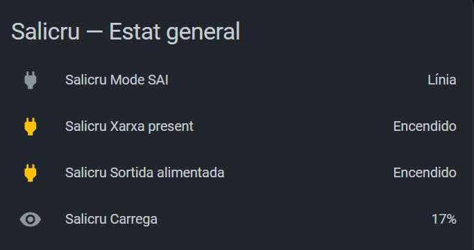
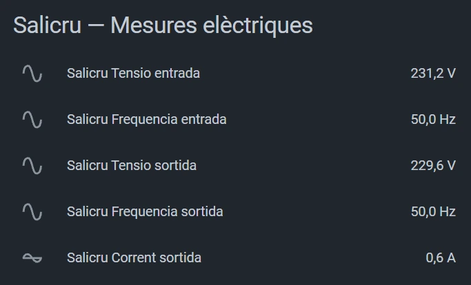
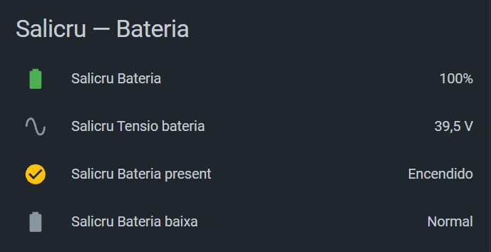
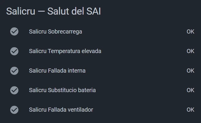
Edit your dashboard and add a manual card. This uses a vertical-stack of four native entities cards, with no custom frontend dependencies. Preserve your other cards and adjust references if you changed entity IDs. The four groups separate general state, electrical measurements, battery, and health/alarms.
type: vertical-stack
cards:
  - type: entities
    title: Salicru — Overview
    show_header_toggle: false
    entities:
      - sensor.salicru_ups_operating_mode
      - binary_sensor.salicru_utility_power_present
      - binary_sensor.salicru_output_powered
      - sensor.salicru_ups_load
  - type: entities
    title: Salicru — Electrical measurements
    show_header_toggle: false
    entities:
      - sensor.salicru_input_voltage
      - sensor.salicru_input_frequency
      - sensor.salicru_output_voltage
      - sensor.salicru_output_frequency
      - sensor.salicru_output_current
  - type: entities
    title: Salicru — Battery
    show_header_toggle: false
    entities:
      - sensor.salicru_battery_level
      - sensor.salicru_battery_voltage
      - binary_sensor.salicru_battery_present
      - binary_sensor.salicru_low_battery
  - type: entities
    title: Salicru — Health and alarms
    show_header_toggle: false
    entities:
      - binary_sensor.salicru_overload
      - binary_sensor.salicru_high_temperature
      - binary_sensor.salicru_internal_fault
      - binary_sensor.salicru_battery_replacement
      - binary_sensor.salicru_fan_fault
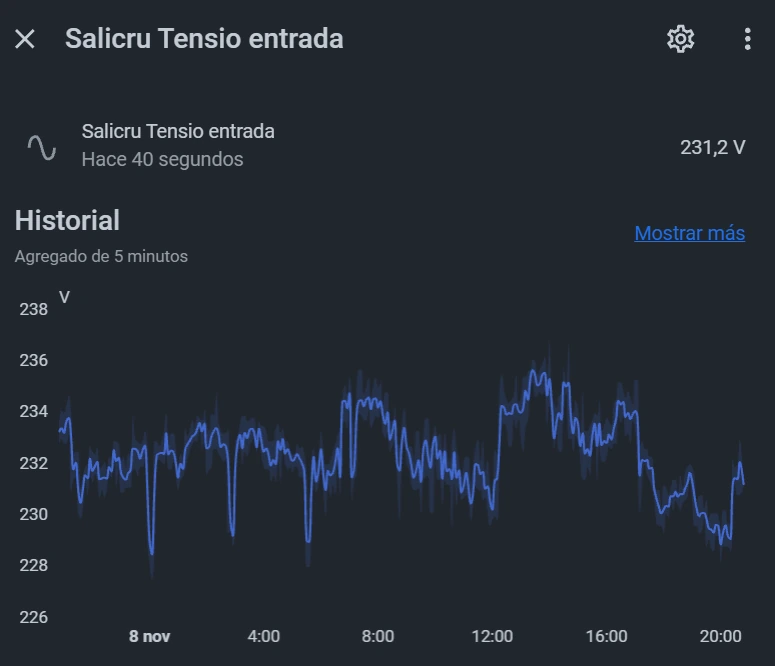
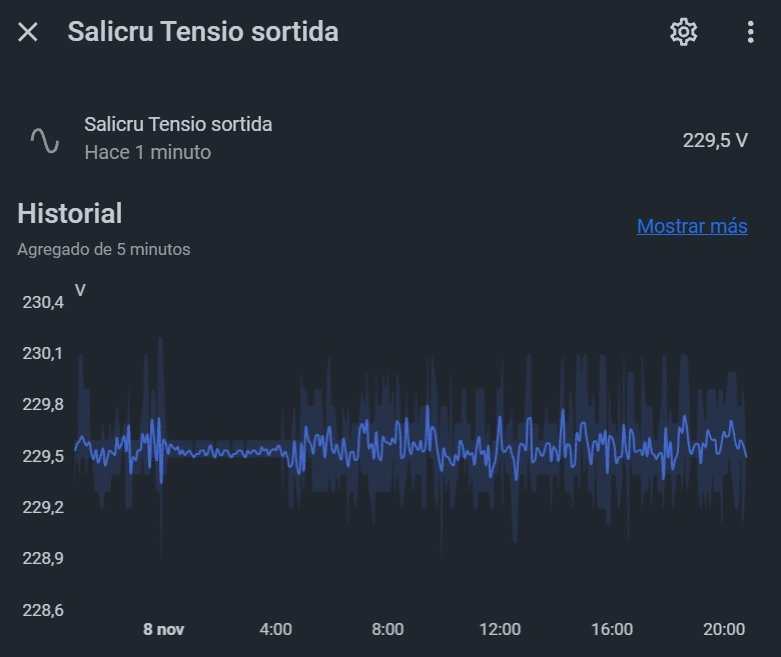
The screenshots below are actual Home Assistant cards, not mockups. Their Catalan names and some Spanish interface labels match the tested installation. The raw mode/status helper sensors are intentionally absent from the dashboard because their numeric words are not useful at a glance.
Step 10. Compare readings and check updates
Nimbus and the physical display provide useful reference readings, but neither is required for local Modbus polling. Compare like with like: output frequency with output frequency, voltage with voltage, and current with current. Volts measure voltage; amps measure current. Do not convert load percentage straight into watts without knowing how the UPS defines it.
The first frequency response was 500 raw and 50.0 Hz in both systems. Battery values of 100% and 39.4 V matched. Output voltage was around 229 V and output current changed with equipment load. These were not synchronized measurements: Nimbus has a timestamp for the measurement, and Home Assistant has its own one-minute polling cycle.
Small differences of tenths of a volt or a few load-percentage points are compatible with different refresh times and changing loads. That is not proof of perfect agreement or calibration. Read Nimbus’s measurement timestamp, not just the screenshot time. Large persistent discrepancies still require checking address, scale, and what the value represents.
Watch more than one update. Constant values do not necessarily change their state timestamp every cycle, and Home Assistant can restore a previous value during startup. We observed voltage and load changing as well as raw protocol responses. Freshness and recovery need their own validation before equipment shutdown logic is added.
Step 11. Troubleshoot the specific symptom
| Symptom | Interpretation | Check next |
|---|---|---|
| Enabled, but unreachable | A saved setting is not a listening-server test. | Persistence, LCD state, log, transport; only consider documented IoT restart. |
| Connection refused / WinError 10061 | TCP was not established; no register has been decoded. | IP, port, service, routing/filter; changing the register will not fix TCP refusal. |
| Timeout | No response within the limit; not necessarily a closed port. | Network reachability, VLAN/filter, service and timing. Avoid broad scans. |
| Wrong or changed IP | You may be addressing another device or an absent host. | Local identification and DHCP assignment. |
| Wrong Unit ID | TCP may work but the request may time out or be rejected. | Documented Unit ID; 1 is our tested value, not universal. |
| Modbus exception | The server understood Modbus but rejected the request. | Exact exception code, supported function and address. Never send a write to fix it. |
| 500 or 2294 displayed as final reading | Scale may be missing. | Map units and scale 0.1; do not apply conversion twice. |
| Valid response, implausible value | Could be format, offset, unsupported field, or placeholder. | Keep bytes and check length/map before adding a sensor. |
| Unavailable sensor | No usable value according to the client or template. | Logs, source word, network, availability; unavailable is not normal. |
| Unknown template during startup | May not be initialized yet. | Wait for startup and inspect template errors; do not overwrite state. |
| Duplicate entity or _2 suffix | Names or hubs may already exist. | One package per example and unique names for another UPS. |
| Mismatch with Nimbus | Refresh schedules differ. | Compare timestamps, units, and persistent behavior. |
| Different Salicru model fails | This map is not universal. | Exact model, communications card and firmware documentation. |
Common Modbus exception codes include 1 (illegal function), 2 (illegal data address), 3 (illegal data value), and 4 (server device failure). General protocol meanings do not replace model documentation. Our script reports the code and stops without trying another register.
If YAML validation fails, do not restart. If entities are missing, check package loading and whether an !include expects a list rather than a complete package. To roll back, restore the previous package or remove the new package file, validate, and restart Core. An isolated package problem does not automatically require restoring all of Home Assistant.
Step 12. Security and automation boundaries
- Keep Modbus on a trusted LAN; do not forward TCP 502 from the internet. Conventional Modbus TCP does not provide HTTPS-style client authentication or encryption.
- Our client reads only FC03 and selected registers. That does not prevent other reachable clients from using any write functions offered by the server.
- Do not share credentials, pairing QR codes, tokens, MAC addresses, serial numbers, or unnecessary home configuration.
- Do not run UPS software that sends startup control commands, and do not trigger battery tests or power changes just to see an alarm.
- Treat unknown/unavailable separately from on/off. A communication failure is not proof that all alarms are clear.
- Do not automatically shut down your NAS based on unvalidated transitions or communication recovery.
Utility power and battery mode can support future outage/restoration notifications. This tutorial does not install critical automations. First verify the real transition, communications loss and recovery, detection latency, and power backup for the host and network. Avoid “power restored” alerts caused only by a Home Assistant restart or an old restored state.
For related background, see Home Assistant entities, states, attributes, and actions and protecting Home Assistant passwords with secrets.yaml. This Modbus hub does not use a password, but your local network is not automatically safe because of that.
What this setup delivers—and what remains unverified
With a compatible Modbus server and the right map, Home Assistant can monitor a UPS locally without continually querying the manufacturer’s cloud. Our RT3 now supplies changing electrical readings, operating mode, and selected status/alarm signals in a useful native dashboard. No firmware update was needed to obtain these results.
The key was not maximizing entity count: it was validating interpretations and excluding doubtful data. Runtime remains unresolved, fault transitions have not all been tested, and another Salicru may need a different map. Start with one documented read, check the units, and expand only when the readings make sense. That gives you a monitoring setup you can explain and maintain.
Primary references and example version
- Salicru IQ14700: registers and alarm-bit definitions.
- Salicru EL22650: RT3 LCD settings.
- Salicru EL28450: integrated IoT and Nimbus connectivity.
- Home Assistant Modbus integration.
- Home Assistant Template integration.
- Home Assistant configuration packages.
- NUT hardware compatibility list for USB alternatives.
Examples derive from our configuration validated on October 13, 2026, with Core 2026.10.1. Screenshots are real, including the input/output histories added later; they do not establish compatibility or fault behavior on other models. Review current documentation if you use a different Home Assistant release.
Continue reading

Next related guide · 4 min read
Tuya in Home Assistant: Smart Life and QR Code Setup
Updated August 27, 2026. Home Assistant’s official Tuya integration no longer requires the Tuya IoT developer-project workflow found in many older guides. The current…
Continue with this article