

Updated August 19, 2026 · Specifications, pinout, power, and ESPHome setup checked for the current LOLIN D1 mini and common clones.
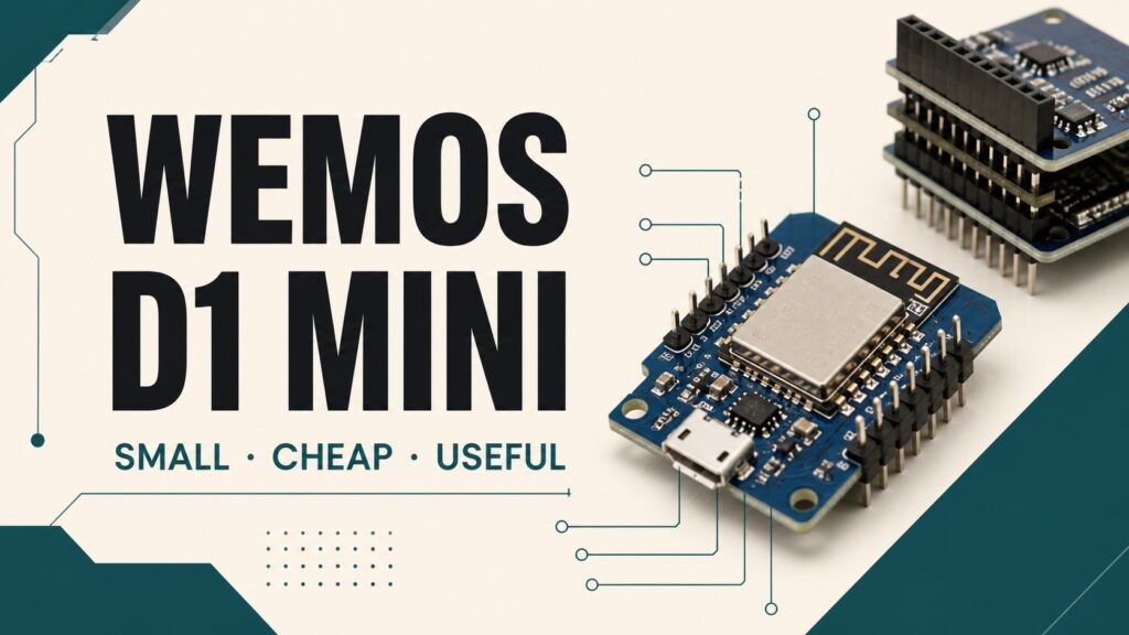
The Wemos D1 mini, officially branded LOLIN D1 mini in recent revisions, is a compact ESP8266 board with USB, a 3.3 V regulator, and 4 MB of flash. Its size and shield ecosystem made it one of the most practical boards for small ESPHome nodes.
It is not an Arduino Uno-class board and should not be confused with D1 mini-shaped ESP32-S2/S3/C3 products. The classic D1 mini uses ESP8266EX. The current official revision has USB-C, while older units and many clones use Micro-USB or different internal parts.
Quick verdict
It is a strong choice for temperature sensors, contacts, relays, I²C, 1-Wire, and basic WiFi automation. It is inexpensive, tiny, and well supported. It is not the best new purchase for Bluetooth, audio, cameras, large displays, or memory-heavy projects; those favor an ESP32 variant.
D1 mini specifications
| Feature | Official LOLIN D1 mini V4 |
|---|---|
| Microcontroller | ESP8266EX |
| Clock | 80/160 MHz |
| Flash | 4 MB |
| Logic | 3.3 V |
| Digital I/O | 11 exposed pins with restrictions |
| Analog input | One, specified at 3.2 V maximum externally |
| USB | USB-C on V4; Micro-USB on older revisions |
| Size | 34.2 × 25.6 mm |
| Weight | About 3 g |
Eleven exposed digital pins do not mean eleven restriction-free GPIOs. Several affect boot, RX/TX are shared with UART, and D0/GPIO16 behaves differently. All signal pins use 3.3 V logic.
Wemos D1 mini pinout
| Label | GPIO | Use and caution |
|---|---|---|
| D0 | GPIO16 | Deep-sleep wake; no normal pull-up and limitations for interrupts/1-Wire |
| D1 | GPIO5 | Common SCL pin and convenient GPIO |
| D2 | GPIO4 | Common SDA pin and convenient GPIO |
| D3 | GPIO0 | Must be HIGH for normal boot |
| D4 | GPIO2 | Must be HIGH at boot; onboard LED on many revisions |
| D5 | GPIO14 | SPI SCLK or GPIO |
| D6 | GPIO12 | SPI MISO or GPIO |
| D7 | GPIO13 | SPI MOSI or GPIO |
| D8 | GPIO15 | Must stay LOW at boot |
| RX/TX | GPIO3/1 | UART; logger can use them |
| A0 | ADC | Input only; do not exceed the board range |
ESPHome accepts labels such as D1 and D2 when the board ID is correct, but GPIO5 and GPIO4 make the configuration explicit and easier to compare with a schematic.
Power: USB, 5V, and 3V3
- USB: powers the board through its regulator and supports programming.
- 5V pin: connects to the USB/VBUS rail depending on revision; follow the schematic.
- 3V3 pin: regulated rail for ESP8266 and low-current peripherals.
- GPIO: 3.3 V signals only, never direct 5 V inputs.
A peripheral that exceeds the regulator’s reasonable output needs a separate supply and common ground. Relays, LED strips, and motors must not be powered directly from a GPIO. WiFi transmit peaks also require a good cable and supply.
Why A0 differs from a bare ESP8266
The ESP8266 chip ADC accepts roughly 0–1 V. The official D1 mini includes a divider and specifies a 3.2 V maximum external input on A0. A bare ESP-12 or clone may differ. Never connect 5 V or copy a voltage range without checking the revision.
Current ESPHome configuration
esphome:
  name: living-room-d1-mini
  friendly_name: Living Room D1 mini

esp8266:
  board: d1_mini
  early_pin_init: false

logger:

api:
  encryption:
    key: !secret api_encryption_key

ota:
  - platform: esphome
    password: !secret ota_password

wifi:
  ssid: !secret wifi_ssid
  password: !secret wifi_password

binary_sensor:
  - platform: gpio
    name: "Button"
    pin:
      number: GPIO4  # D2
      mode:
        input: true
        pullup: true
      inverted: true
    filters:
      - delayed_on_off: 30ms
board: d1_mini applies the expected board mapping. early_pin_init: false can reduce early output pulses during a restart, but relay hardware still needs safe biasing and isolation.
First flash and OTA
- Use a USB data cable rather than a charge-only cable.
- Select D1 mini/ESP8266 in Device Builder.
- Install over USB and watch the logs.
- Add the discovered node to Home Assistant.
- Use protected OTA for later updates.
The official V4 uses a CH340C USB bridge; some systems need its driver. A missing serial port often points to the cable, driver, connector, or a bad clone rather than YAML.
Shields and clones
The D1 mini form factor has shields for relays, displays, sensors, and power. Check voltage, assigned pin, and connector height: two shields can request the same GPIO or I²C address.
A clone may work perfectly, but do not assume it reproduces the official USB protection, regulator, A0 divider, or flash. For a permanent installation, inspect soldering, power behavior, and regulator temperature.
Advantages and limitations
| Advantages | Limitations |
|---|---|
| Very compact and inexpensive | ESP8266 memory and CPU limits |
| Integrated USB and regulator | No Bluetooth |
| 4 MB flash on the official board | Only one ADC |
| Large shield ecosystem | Several pins affect boot |
| Excellent ESPHome support | Clones use variable parts |
Troubleshooting
| Problem | Check |
|---|---|
| No USB serial port | Data cable, CH340 driver, and connector |
| Won’t boot with a module attached | D3/D4/D8 and required boot levels |
| Resets during WiFi or relay use | Power supply, regulator, cable, and ground |
| A0 always reads maximum | Input voltage exceeds the board range |
| Onboard LED works backwards | D4 is active-low on many revisions |
| A shield does not respond | Pin, address, revision, and conflicts |
D1 mini or ESP32?
Choose D1 mini for a small basic WiFi node or when you already have compatible shields. Choose an ESP32-C3/S3 board when you need Bluetooth, native USB, more memory, or additional peripherals.
Related guides
- Secure ESPHome WiFi configuration and troubleshooting.
- Secure ESPHome OTA updates.
- DS18B20 with ESP8266 and ESPHome.
Checked sources
Frequently asked questions
Are D1 mini GPIOs 5 V tolerant?
No. Logic is 3.3 V. USB/5V feeds the regulator but does not change signal limits.
Can I use D1 and GPIO5 interchangeably?
With board: d1_mini, D1 maps to GPIO5. Writing GPIO5 is more explicit and portable.
Is it still worth buying?
Yes for basic inexpensive WiFi nodes. Compare it with an ESP32 board before starting a project expected to grow.
The D1 mini remains excellent when simplicity is the advantage. Identify the revision, respect boot pins, and treat every signal as 3.3 V to avoid the most common failures.
Continue reading
Next related guide · 9 min read
ESP32 Guide: Pinout, Boards and ESPHome Setup (2026)
Updated August 3, 2026. I reviewed the specifications, restricted GPIOs, and every YAML example against the current Espressif and ESPHome documentation. The ESP32 remains…
Continue with this article