
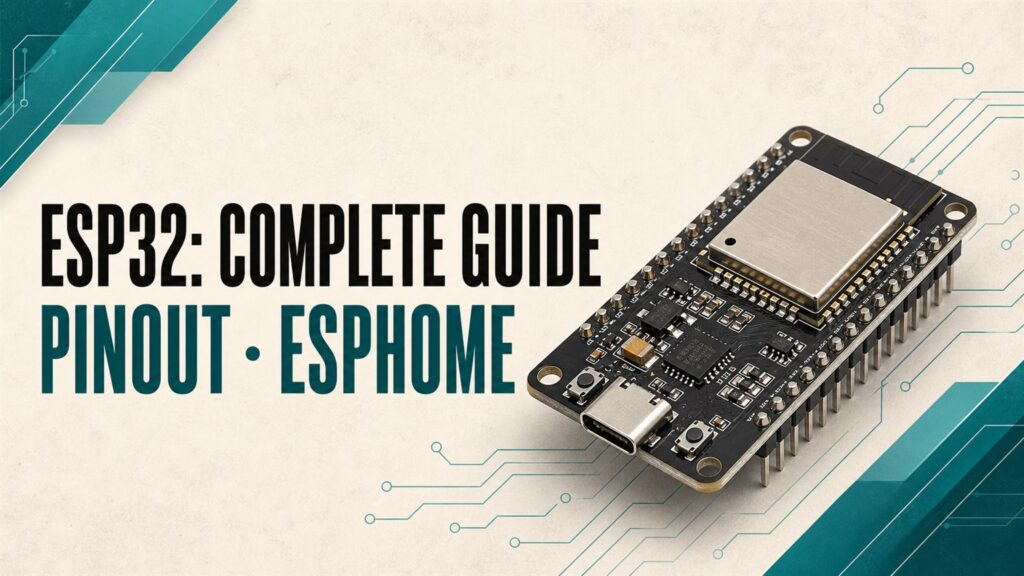

Updated August 3, 2026. I reviewed the specifications, restricted GPIOs, and every YAML example against the current Espressif and ESPHome documentation.
The ESP32 remains one of the best platforms for building local sensors, controllers, and DIY devices with ESPHome and Home Assistant. It combines 2.4 GHz Wi-Fi, Bluetooth, a broad set of peripherals, and enough processing power for projects that would quickly outgrow an ESP8266.
However, “ESP32” no longer describes one board. It may refer to the original chip, a module such as the ESP32-WROOM-32, a development board, or a wider family that includes C3, S2, S3, and C6 variants. This guide explains the differences, how to choose a board, which pins require special care, and how to build a current, secure ESPHome configuration.
What is an ESP32? Chip, module, and development board
- Chip or SoC: the Espressif device containing the processor, radios, internal memory, and peripherals.
- Module: combines the chip with flash, a crystal, an antenna, and supporting components. ESP32-WROOM-32 is a familiar example.
- Development board: adds a voltage regulator, USB-to-serial interface, BOOT/EN buttons, and headers so the module is easy to power and program.
This distinction matters. Two products advertised as “ESP32 boards” may expose a different number of pins, use a different USB interface, include different amounts of memory, or even use chip variants that require different ESPHome board profiles.
Original ESP32 specifications
The original ESP32 is still a mature and capable choice. According to the official Espressif datasheet, its major features include:
| Feature | Original ESP32 |
|---|---|
| Processor | Single- or dual-core Xtensa LX6, up to 240 MHz depending on the model |
| Wireless | 2.4 GHz 802.11 b/g/n Wi-Fi, Bluetooth Classic 4.2, and BLE 4.2 |
| Internal memory | 448 KB ROM, 520 KB SRAM, and 16 KB RTC SRAM |
| GPIO | Up to 34 physical GPIOs, with restrictions depending on module and board |
| Analog | 12-bit SAR ADC with up to 18 channels; two 8-bit DAC channels |
| Peripherals | I²C, SPI, UART, I²S, PWM, RMT, pulse counter, touch, and TWAI |
| Wired networking | Built-in Ethernet MAC; requires an external PHY and a compatible board |
| Native USB | No; typical boards use a USB-to-serial converter |
Chip specifications do not automatically describe the complete board. A manufacturer may reserve pins for flash, PSRAM, a camera, display, or Ethernet interface. Always check the schematic and pinout for your exact model.
ESP32 vs. C3, S3, and C6
| Family | Good fit for | Important detail |
|---|---|---|
| Original ESP32 | General ESPHome projects, Bluetooth Classic, mature support, and a large example library | No native USB |
| ESP32-C3 | Compact low-cost Wi-Fi/BLE sensor nodes and modern ESP8266 replacements | Single-core RISC-V and fewer GPIOs than many classic boards |
| ESP32-S3 | Displays, audio, cameras, PSRAM, and projects that benefit from native USB | BLE only; no Bluetooth Classic |
| ESP32-C6 | New projects requiring Wi-Fi 6, BLE, or an 802.15.4 radio | Verify ESPHome component support before buying |
For a first home ESPHome project, a well-documented original ESP32 or ESP32-C3 board is usually the easiest starting point. ESPHome can begin with a generic family selection and let you refine the exact board later. The official Understanding Boards guide explains why selecting the right profile matters.
How to choose an ESP32 development board
- Variant and memory: confirm the actual chip, flash capacity, and whether the board includes PSRAM.
- USB connector: USB-C is convenient, but the connector alone does not mean the chip has native USB.
- USB-to-serial chip: CP2102, CH340, and similar interfaces generally work well, although a driver may be required.
- Voltage regulator: it affects stability, sensor power, and real deep-sleep current.
- Board width: some boards cover most of a breadboard and leave little room for jumper wires.
- Pinout and schematic: avoid undocumented boards when dependable operation matters.
- Power and extras: decide whether you need battery charging, Ethernet, a camera, or an external antenna.
ESP32 pinout: GPIOs that require extra care
There is no universal pinout for every ESP32 board. The diagram below represents one specific development board and is only useful if its labels match yours.

- GPIO6 through GPIO11: normally connect to flash memory. Do not use them.
- GPIO34 through GPIO39: input-only pins with no internal pull-up or pull-down resistors.
- GPIO0, 2, 5, 12, and 15: boot-strapping pins. The wrong level during startup can prevent the board from booting.
- GPIO1 and GPIO3: commonly used for serial logging and programming.
- ADC2: shares resources with Wi-Fi on the original ESP32. For analog sensors with Wi-Fi enabled, prefer ADC1 channels, typically GPIO32 through GPIO39.
These limitations are documented in Espressif’s official ESP32 GPIO reference. Other ESP32 variants have different restrictions, so do not reuse this list without checking their documentation.
How much power does an ESP32 really use?
The original ESP32 chip datasheet lists approximately 10 µA in deep sleep under its test conditions. A complete development board draws more because of its regulator, USB-to-serial interface, power LED, and attached sensors. Quoting the chip figure as the guaranteed consumption of a board is misleading.
This is rarely critical for a device powered continuously over USB. It matters greatly on batteries: choose a board designed for low power, remove unnecessary loads, and measure the complete assembly. Active Wi-Fi creates current peaks, so a weak power supply can cause resets and seemingly random failures.
Current secure ESPHome configuration for ESP32
The legacy format that placed platform: ESP32 under esphome: must not be used anymore. ESP32 now has its own top-level block. The following example targets a generic board using the original ESP32; replace board: with the correct ID for your hardware.
esphome:
  name: esp32-living-room
  friendly_name: Living Room ESP32

esp32:
  board: esp32dev
  framework:
    type: esp-idf

logger:
  level: INFO

api:
  encryption:
    key: !secret esp32_living_room_api_key

ota:
  - platform: esphome
    password: !secret esp32_living_room_ota_password

wifi:
  ssid: !secret wifi_ssid
  password: !secret wifi_password

sensor:
  - platform: wifi_signal
    name: "Wi-Fi Signal"
    update_interval: 60s
Current ESPHome releases recommend ESP-IDF for supported ESP32 projects. Declaring it explicitly makes the example’s intent clear. If a particular component requires Arduino, change only the framework type after checking that component’s documentation.
The secrets.yaml file
wifi_ssid: "Your Wi-Fi name"
wifi_password: "Your Wi-Fi password"
esp32_living_room_api_key: "BASE64_KEY_GENERATED_BY_ESPHOME"
esp32_living_room_ota_password: "a-long-unique-password"
esp32_living_room_web_username: "admin-esp32-living-room"
esp32_living_room_web_password: "another-long-unique-password"
Do not copy the placeholder API key. The ESPHome wizard generates a valid 32-byte Base64 key. Use a unique API key, OTA password, and web credential set for every device. Our ESPHome substitutions and packages guide explains how to reuse YAML without exposing secrets.
Secure web_server configuration
web_server provides browser-based status and control, but it also creates another control surface on your local network. ESPHome’s Security Best Practices recommend leaving it disabled unless needed and always enabling authentication when it is used.
web_server:
  port: 80
  version: 3
  auth:
    username: !secret esp32_living_room_web_username
    password: !secret esp32_living_room_web_password
    type: digest
  ota: false
This keeps password-protected native OTA available while disabling firmware uploads through the web interface. Never expose an ESPHome web server directly to the internet. Even with authentication, ESPHome is designed for trusted networks and benefits from an isolated IoT network or VLAN.
OTA became a platform component in ESPHome 2024.6, so the current native configuration includes - platform: esphome. Browser uploads are available through - platform: web_server, but they require careful security decisions and protected web access. See the official OTA documentation for the current behavior.
Installing your first ESP32 with ESPHome
- Connect the board with a USB cable that supports data, not just charging.
- In ESPHome Device Builder, select New device and choose the correct board family.
- Perform the first installation over USB. Some boards require holding BOOT when the upload begins.
- After the device joins Wi-Fi, Home Assistant should discover it. Add it through the ESPHome integration.
- Check entities, logs, and Wi-Fi signal before connecting relays, motors, or external sensors.
- Future firmware updates can use the protected OTA connection.
Common ESP32 problems
The board does not appear over USB
Try another data cable and USB port, then check the CP210x or CH34x driver. Close any software that may already be using the serial port.
ESPHome reports a board or framework error
Read the exact variant printed on the module and verify the board ID. esp32dev is not a universal value for C3, S2, S3, C6, or specialty boards.
The ESP32 resets when Wi-Fi or a relay activates
This usually points to an inadequate power supply, voltage drop, poor grounding, or electrical noise. Never drive a motor or relay coil directly from a GPIO. Our ESPHome relay module guide covers safer wiring.
An analog sensor stops working when Wi-Fi connects
On the original ESP32, move the signal to an ADC1 channel and verify the input voltage. This limitation often appears in analog projects such as our MQ-2 ESPHome guide.
Recommended ESP32 projects
- BMP280 with ESP32 and ESPHome: temperature and pressure over I²C.
- BME280 with ESPHome and Home Assistant: adds humidity measurement.
- Home Assistant Bluetooth Proxy with ESPHome: extend BLE coverage around your home.
ESP32 review verdict
The original ESP32 remains an excellent choice in 2026 because it is mature, affordable, and supported by a huge ecosystem. For an ordinary ESPHome node, it provides more headroom than an ESP8266 while adding Bluetooth, more GPIOs, and advanced peripherals. Newer C3, S3, and C6 devices broaden the options but make board compatibility and pinout verification more important.
The best board is not the one with the longest specification list. It is the one with clear documentation, stable power, and the right interfaces for your project. Start with a minimal YAML file, protect API, OTA, and web access, then add hardware one component at a time.
ESP32 FAQ
Does ESP32 work directly with Home Assistant?
Yes. After installing ESPHome, Home Assistant can discover the device and communicate through the encrypted native API.
Can I power an ESP32 with 5 volts?
Many development boards accept 5 V through USB or a VIN/5V pin because they include a regulator. The chip and its GPIOs operate at 3.3 V and are not 5 V tolerant. Always check the board schematic.
Do I need web_server for Home Assistant?
No. Home Assistant communicates through ESPHome’s native API. Enable web_server only when browser access is useful, and protect it with authentication.
Does esp32dev work for every ESP32 board?
No. It is a common generic profile for boards based on the original ESP32. C3, S2, S3, C6, and many specialty boards require their own board ID or variant.
Technical sources: official ESPHome documentation for the ESP32 platform, Web Server, and OTA, plus Espressif hardware documentation. Always verify the documentation for your exact chip variant and board.
Continue reading
Next related guide · 9 min read
ESPHome OTA Updates: Secure Setup and Troubleshooting (2026)
Updated August 3, 2026. I reviewed this entire guide for the changes introduced in ESPHome 2024.6, 2025.7, and 2026.1, and removed passwords written directly…
Continue with this article